- 您现在的位置:买卖IC网 > Sheet目录871 > OKL-T/3-W12P-C (Murata Power Solutions Inc)CONV DC/DC 15W 12VIN 3AOUT SMD
�� �
�
�OKL-T/3-W12� Series�
�Programmable� Output� 3-Amp� i� LGA� SMT� PoLs�
�drop,� thereby� shutting� down� the� PWM� controller.� Following� a� time-out� period,�
�the� PWM� will� restart,� causing� the� output� voltage� to� begin� rising� to� its� appropri-�
�OKL� N� Module�
�ate� value.� If� the� short-circuit� condition� persists,� another� shutdown� cycle� will�
�initiate.� This� rapid� on/off� cycling� is� called� “hiccup� mode”.� The� hiccup� cycling�
�reduces� the� average� output� current,� thereby� preventing� excessive� internal�
�temperatures� and/or� component� damage.�
�The� “hiccup”� system� differs� from� older� latching� short� circuit� systems�
�+Vin�
�Rp�
�+Vin�
�On/Off�
�Q3�
�E�
�PWM�
�GND�
�because� you� do� not� have� to� power� down� the� converter� to� make� it� restart.� The�
�system� will� automatically� restore� operation� as� soon� as� the� short� circuit� condi-�
�tion� is� removed.�
�Remote� On/Off� Control�
�Q1�
�The� OKL� Series� power� modules� can� be� speci?ed� with� either� a� positive� or� negative�
�logic� type.� See� Figures� 7� and� 8� for� On/Off� circuit� control.� In� the� positive� logic� on/off�
�option� the� unit� turns� on� during� a� logic� high� on� the� On/Off� pin� and� turns� off� during� a�
�logic� low.� In� a� negative� logic� on/off� option,� the� unit� turns� off� during� logic� high� and�
�on� during� logic� low.� The� On/Off� signal� should� always� be� reference� to� ground.� For�
�positive� or� negative� option,� leaving� then� On/Off� pin� disconnected� will� turn� the� unit�
�GND�
�GND�
�BOM� ?� Rp� ?� 20K�
�BOM� ?� Q1� ?� Q� SMT� MOS� P� 30V�
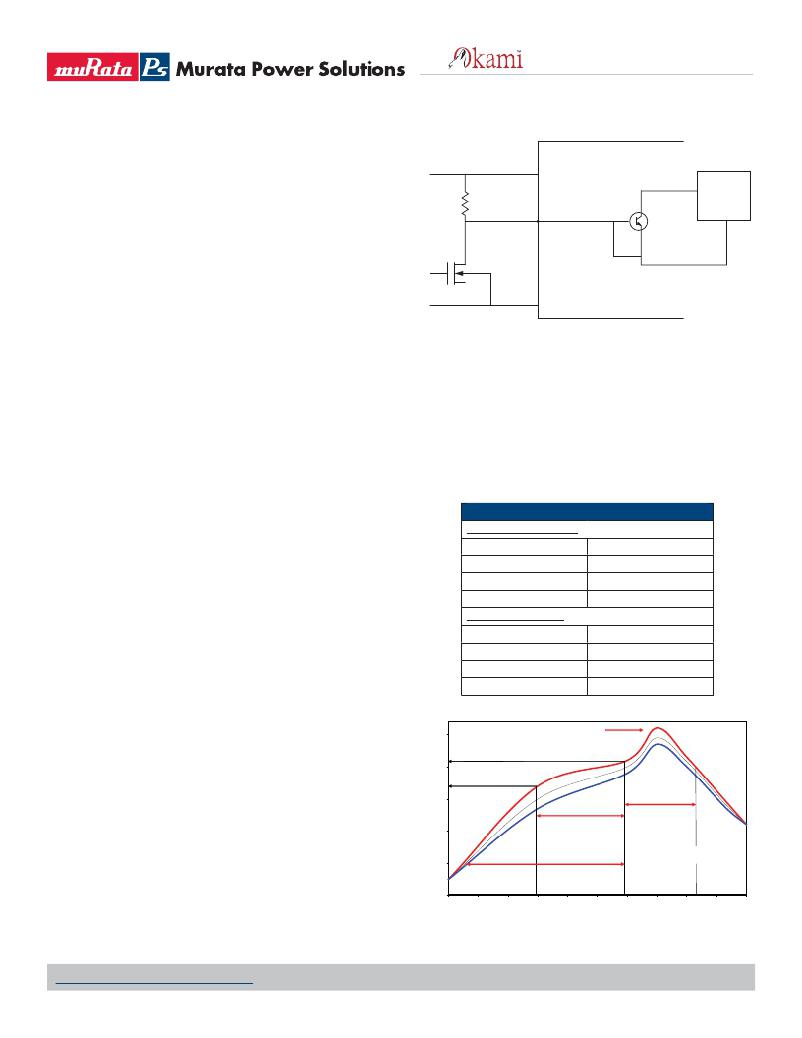
�Figure� 8.� On/Off� Circuit� Control� for� Using� Negative� On/Off� Logic�
�on� when� input� voltage� is� present.�
�Positive—Units� are� enabled� when� the� on/off� pin� is� left� open� or� is� pulled� high�
�to� +Vin.� The� On/Off� circuit� control� is� shown� in� ?gure� 7.� When� the� external� tran-�
�sistor� Q1� is� in� the� off� state,� the� internal� PWM� enable� pin� is� pull� high� causing� the�
�unit� to� turn� on.� When� Q1� is� turn� on,� the� On/Off� pin� is� pulled� low� and� the� units� is�
�off.� Rp� should� be� around� 20K� ohms.�
�Negative—Units� are� enabled� when� the� ON/Off� is� open� or� brought� to� within�
�a� low� voltage� (see� speci?cations)� with� respect� to� –Vin.� The� unit� is� off� when�
�Soldering� Guidelines�
�Murata� Power� Solutions� recommends� the� speci?cations� below� when� installing� these�
�converters.� These� speci?cations� vary� depending� on� the� solder� type.� Exceeding� these�
�speci?cations� may� cause� damage� to� the� product.� Your� production� environment� may� differ�
�therefore� please� thoroughly� review� these� guidelines� with� your� process� engineers.�
�Reflow� Solder� Operations� for� surface-mount� products� (SMT)�
�For Sn/Ag/Cu based solders:�
�the� ON/Off� is� pulled� high� with� respect� to� –Vin� (see� speci?cations).� The� On/�
�Off� circuitry� is� shown� in� ?gure� 8.� The� On/Off� pin� should� be� pulled� high� with� an�
�external� pull-up� resistor� (20K� ohms).� When� Q1� is� in� the� off� state,� the� On/Off� pin�
�is� pulled� high,� transistor� Q3� is� turn� on� and� the� unit� is� off.� To� turn� on� the� unit,�
�Q1� is� turn� on,� pulling� the� On/Off� pin� low� and� turning� Q3� off� resulting� on� the� unit�
�being� on.�
�Dynamic� control� of� the� On/Off� function� should� be� able� to� sink� the� speci-�
�?ed� signal� current� when� brought� low� and� withstand� appropriate� voltage� when�
�brought� high.� Be� aware� too� that� there� is� a� ?nite� time� in� milliseconds� (see� speci-�
�?cations)� between� the� time� of� On/Off� Control� activation� and� stable,� regulated�
�output.� This� time� will� vary� slightly� with� output� load� type� and� current� and� input�
�conditions.�
�Preheat� Temperature�
�Time� over� Liquidus�
�Maximum� Peak� Temperature�
�Cooling� Rate�
�For Sn/Pb based solders:�
�Preheat� Temperature�
�Time� over� Liquidus�
�Maximum� Peak� Temperature�
�Cooling� Rate�
�Less� than� 1� oC.� per� second�
�45� to� 75� seconds�
�260� oC.�
�Less� than� 3� oC.� per� second�
�Less� than� 1� oC.� per� second�
�60� to� 75� seconds�
�235� oC.�
�Less� than� 3� oC.� per� second�
�Output� Capacitive� Load�
�These� converters� do� not� require� external� capacitance� added� to� achieve�
�rated� speci?cations.� Users� should� only� consider� adding� capacitance� to� reduce�
�250�
�200�
�Peak� Temp.�
�235-260°� C�
�switching� noise� and/or� to� handle� spike� current� load� steps.� Install� only� enough�
�capacitance� to� achieve� noise� objectives.� Excess� external� capacitance� may�
�cause� regulation� problems,� degraded� transient� response� and� possible� oscilla-�
�tion� or� instability.�
�150�
�100�
�Soaking� Zone�
�120� sec� max�
�Re?ow� Zone�
�time� above� 217°� C�
�45-75� sec�
�50�
�<1.5°� C/sec�
�Preheating� Zone�
�High� trace� =� normal� upper� limit�
�Low� trace� =� normal� lower� limit�
�240� sec� max�
�0�
�0�
�30�
�60�
�90�
�120�
�150�
�180�
�210�
�240�
�270�
�300�
�Time� (sec)�
�Recommended� Lead-free� Solder� Re?ow� Pro?le�
�www.murata-ps.com/support�
�MDC_OKL-T/3-W12� Series.B01� Page� 16� of� 17�
�发布紧急采购,3分钟左右您将得到回复。
相关PDF资料
OKL-T/3-W5N-C
CONV DC/DC 9.9W 3A 5VIN SMD
OKL-T/6-W12N-C
CONV DC/DC 30W 6A 12VIN SMD
OKL-T/6-W5N-C
CONV DC/DC 19.8W 6A 5VIN SMD
OKR-T/10-W12-C
CONV DC/DC 10A 12VIN POL SIP
OKR-T/3-W12-C
CONV DC/DC 15W 12VIN SIP
OKR-T/6-W12-C
CONV DC/DC 6A 12VIN POL SIP
OKX-T/3-D12N-C
DC-DC CONVRT 0.7525-5.5V 3A 5SIP
OKX-T/3-W5P-C
DC-DC CONVRT 0.7525-3.6V 3A 5SIP
相关代理商/技术参数
OKL-T/3-W12P-C
制造商:Murata Power Solutions 功能描述:DC/DC Converter
OKL-T/3-W5
制造商:Murata Power Solutions 功能描述:- Rail/Tube
OKL-T/3-W5N-C
功能描述:DC/DC转换器 5Vin 0.6-3.63Vout 3A 9.9W Neg Polarity
RoHS:否 制造商:Murata 产品: 输出功率: 输入电压范围:3.6 V to 5.5 V 输入电压(标称): 输出端数量:1 输出电压(通道 1):3.3 V 输出电流(通道 1):600 mA 输出电压(通道 2): 输出电流(通道 2): 安装风格:SMD/SMT 封装 / 箱体尺寸:
OKL-T/3-W5P-C
功能描述:DC/DC转换器 5Vin 0.6-3.63Vout 3A 9.9W Pos Polarity
RoHS:否 制造商:Murata 产品: 输出功率: 输入电压范围:3.6 V to 5.5 V 输入电压(标称): 输出端数量:1 输出电压(通道 1):3.3 V 输出电流(通道 1):600 mA 输出电压(通道 2): 输出电流(通道 2): 安装风格:SMD/SMT 封装 / 箱体尺寸:
OKL-T/6-W12N-C
功能描述:DC/DC转换器 12Vin .59-5.5Vout 6A 30W Neg Polarity
RoHS:否 制造商:Murata 产品: 输出功率: 输入电压范围:3.6 V to 5.5 V 输入电压(标称): 输出端数量:1 输出电压(通道 1):3.3 V 输出电流(通道 1):600 mA 输出电压(通道 2): 输出电流(通道 2): 安装风格:SMD/SMT 封装 / 箱体尺寸:
OKL-T/6-W12N-C
制造商:Murata Power Solutions 功能描述:DC/DC Converter
OKL-T/6-W12P-C
功能描述:DC/DC转换器 12Vin .59-5.5Vout 6A 30W Pos Polarity
RoHS:否 制造商:Murata 产品: 输出功率: 输入电压范围:3.6 V to 5.5 V 输入电压(标称): 输出端数量:1 输出电压(通道 1):3.3 V 输出电流(通道 1):600 mA 输出电压(通道 2): 输出电流(通道 2): 安装风格:SMD/SMT 封装 / 箱体尺寸:
OKL-T/6-W5
制造商:MURATA 制造商全称:Murata Manufacturing Co., Ltd. 功能描述:Programmable Output 6-Amp iLGA SMT PoLs